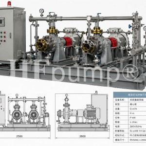
What should be considered when using pumps in parallel? Some experiences from our design of API610 chemical process pumps
2026-06-18 19:27:26 250 江苏海珐In chemical plants, oil refineries, power plant circulating systems, coal chemical projects, and water treatment facilities, parallel operation of pumps is a common design approach. Many users ask me when selecting pumps: "If two pumps are running in parallel, does the flow rate simply double?" Based on our practical experience with API610 chemical process pumps, this question cannot be simplistically answered as "multiply one pump's flow by two." The essence of parallel pump operation is that two or more pumps jointly supply liquid to the same pipeline network under the same discharge pressure or head conditions. Theoretically, parallel operation can increase system flow; however, in actual operation, the final flow depends on the pump performance curve, pipeline resistance curve, valve opening, discharge pressure, medium characteristics, and control method. If these conditions are not calculated in advance, parallel pumps may experience issues such as one pump handling more load while the other handles less, or even backflow, vibration, overload, and mechanical seal damage. As technical personnel at Jiangsu Haifa Machinery Manufacturing Co., Ltd., we typically evaluate whether pumps are suitable for parallel operation from the following aspects in the selection and design of API610 petrochemical process pumps, OH2 chemical pumps, BB2 heavy-duty process pumps, BB3 multistage centrifugal pumps, BB4 multistage pumps, etc.
First, confirm the purpose of parallel operation—do not parallel pumps just for the sake of "having an extra pump." Parallel pump operation generally serves several purposes: first, when the process flow varies significantly, with one pump running at low load and two at high load; second, when the system needs to expand later, and the existing single pump's flow is insufficient, an additional pump of the same specification; third, when the unit requires continuous production, needing one-in-operation-one-on-standby or two-in-operation-one-on-standby; fourth, when some process sections prefer not to select an overly large single pump but aim to improve adjustment flexibility through combined operation of multiple pumps. However, parallel operation is not suitable for all conditions. If the system primarily lacks head rather than flow, parallel operation should not be the first consideration; instead, series operation, increasing the number of impeller stages, or reselection should be considered. operation mainly addresses "insufficient flow," while series operation mainly addresses "insufficient." This must be clarified during the planning stage.
The performance curves of parallel pumps should be similar; it is best to select pumps of the same model and specification. For parallel operation, the ideal approach is to choose pumps with the same model, speed, impeller diameter, sealing scheme, and material configuration. This ensures that the performance curves of the two pumps are basically consistent, flow distribution is balanced, and on-site operation is easier to control. If the performance of the two pumps differs significantly, for example, one has high head and the other low head, when operating on the same discharge pipeline network, the high-head pump will bear more flow, while the low-head pump may be underpowered. In severe cases, it may be "suppressed" by the discharge network, leading to low-flow operation, heating, vibration, or even backflow. This risk cannot be ignored, especially under high-temperature, high-pressure,, explosive, or highly corrosive medium conditions. For example, our company's API610-OH2/HES series petrochemical process pumps cover a flow range of 2 to 2600 m³/h, a head range of up to approximately 300 m, an applicable temperature range of -80 to 450°C, and design pressure of 2.5 MPa to 26 MPa. For such single-stage overhung chemical process pumps, if the project requires parallel operation, we will focus on checking the curve differences between the two pumps at the rated point, minimum continuous stable flow point, shut-off point, and high-flow point to avoid one pump operating outside the high-efficiency zone for extended periods.
Do not only look at the flow of a single pump; consider the system operating point after parallel operation. Many on-site issues are not caused by the pumps themselves but by miscalculations of the pipeline system. After two pumps are paralleled, each pump cannot maintain its original rated flow. Because the total flow increases, pipeline friction losses rise significantly, the system resistance curve becomes steeper, and the actual intersection point moves to a new position. For a simple example: if a single pump's rated flow is 100 m³/h, after two pumps are paralleled, the total system flow may not be 200 m³/h; it might be only 160 m³/h, 170³/h, or even lower. This is because resistance from pipe diameter, elbows, valves, heat exchangers, filters, nozzles, etc., all limit the final flow. Therefore, when selecting pumps for parallel operation, we always require users to provide complete pipeline, including suction tank liquid level, suction pipe length, discharge pipe length, pipe diameter, number of valves, filter pressure drop, heat exchanger pressure drop, and equipment inlet pressure requirements. Only by comparing the system resistance curve with the pump performance curve can we determine whether parallel operation is truly effective.
A check valve must be installed at the discharge of each pump to prevent backflow and reverse rotation. The discharge check valve for parallel pumps is very important. Each pump should have its own check valve at the discharge, and the check valve should be selected based on the medium, pressure, pipe diameter, and start-stop frequency. Its function is to prevent liquid from the running pump from flowing back into the stopped pump when one pump is shut down, which could cause impeller reverse rotation, bearing damage, reverse pressure on the mechanical seal, or even impact on the pump casing. In high-temperature, highly corrosive, particle-containing media, or high-pressure, the selection of the check valve should not only consider the diameter and pressure rating but also the closing response, disc impact, sealing surface material, and water hammer risk. For API610 chemical process pumps, we usually recommend installing a shut-off valve after the discharge check valve to facilitate isolation for single pump maintenance.
Suction conditions must be adequate to prevent parallel pumps from "competing for liquid." The most overlooked aspect of parallel pumps is the suction side conditions. When two pumps operate simultaneously, the total suction flow increases. If the suction pipe diameter is too small the suction liquid level is insufficient, the filter is clogged, or the inlet pipeline layout is unreasonable, it may lead to insufficient net positive suction head (NPSH). Cavitation directly affects centrifugal pumps: flow drop, head fluctuation, increased vibration, impeller cavitation erosion, and unstable mechanical seal faces. For media such as high-temperature liquids, easily vaporized media, low-temperature media, or media near saturation vapor pressure, the cavitation risk is higher. Therefore, the design of the suction header for parallel pumps should be more cautious than for a single pump. We generally recommend keeping the suction header flow velocity low, minimizing elbows and local resistance, ensuring sufficient flow area for the inlet filter, and recording the inlet pressure changes of each pump during commissioning when operating alone and simultaneously. When suction conditions are unstable, blindly increasing the number of parallel pumps is not recommended.
The start-up sequence should be reasonable to avoid instantaneous impact and overload. The start-up of parallel pumps cannot be done arbitrarily. Generally, the first pump should be started first, and after the flow, pressure, current, and vibration stabilize, the second pump can be started. Before starting the second pump, the status of the discharge valve, valve, and pipeline network pressure should be confirmed to prevent impact at the moment of start-up. For high-power pumps, high-head pumps, or high-pressure pipeline networks, it is recommended to configure variable frequency start, soft start, or automatic control logic to avoid excessive motor starting current and reduce pipeline water hammer. When stopping the pumps, attention should also be paid to sequence. Typically, the is gradually reduced first, then one pump is stopped, and finally, based on process requirements, either a single pump is kept running or all are shut down.
Special attention should be paid to low conditions; pumps should not be allowed to run under backpressure for extended periods. In low-load conditions for parallel pumps, if both pumps are running simultaneously, the flow allocated to each pump may fall below the minimum continuous stable flow. At this point, although the pump is still rotating, internal recirculation, heating, and increased radial force occur, affecting the mechanical seal, bearings, and impeller. Our company's API610-OH2-HES(X) low-flow, high-head chemical process pumps have a flow range of 0.8 to 12.5 m³/h, a head range of 12 to 125 m, an applicable temperature range of -80 to 450°C, and a design pressure of up to approximately 2.5 MPa. For such low-flow, high-head conditions, we greater emphasis on minimum flow protection, recirculation line design, and discharge pressure fluctuation. If users require parallel operation, we generally recommend configuring an automatic recirculation valve or a minimum flow bypass line to the pump from operating in the low-flow zone for extended periods.
For parallel operation under high-temperature and high-pressure conditions, special consideration should be given to thermal stress in the pump casing, seals, and piping. In applications such as oil refining, coal chemical, natural gas processing, tower bottom oil, lean solution, rich solution, and high-temperature hot water, parallel pumps must consider not only hydraulic performance but also thermal expansion, pipeline stress, seal flush cooling, and bearing temperature rise. For example, our company's API-BB2 HFDD series heavy-duty petrochemical process pumps have a flow range of 50 to 4000 m³/h, a head range of up to 650 m, an applicable temperature range of -80 to 450°C, and a design pressure of 5.0 MPa to 15.0 MPa. These are commonly used in continuous operation scenarios such as oil refining, petrochemical, coal chemical, crude oil transportation, and high-temperature tower bottoms. If such pumps are operated in parallel, we pay special attention to the center support structure, inlet and outlet pipeline loads, coupling alignment, mechanical seal flush scheme, and bearing cooling method. For higher-head multistage pumps such as the API-BB3 HSSC/HDSC series, with flow ranges covering 10 to 1500 m³/h or 45 to 1440 m³/h, heads exceeding 3000 m, and maximum design pressures up to 35 MPa, parallel control must be more cautious when used in boiler feed water, oilfield water injection, high-pressure transportation, etc. Special attention is needed to prevent pressure fluctuations, water hammer, and reverse pressure on a single pump during start-up and shutdown.
The control method should match the process; manual valve adjustment alone is not recommended. Parallel pump systems should ideally be equipped with monitoring points for pressure, flow, current, bearing temperature, vibration, and seal leakage. For conditions with significant flow fluctuations, variable frequency control, one-drive-one control, or one fixed-speed and one variable-speed pump can be used. For continuous production units, standby pumps can be automatically started or stopped based discharge pressure or flow., the control logic should not rely solely on discharge pressure. A stable discharge pressure does not mean both pumps are operating at reasonable operating points. On-site attention should also be paid to the current of a single pump deviates excessively, whether bearing temperature rises, whether there is abnormal noise from the pump casing, whether the mechanical seal leaks, and whether the inlet pressure drops. If the current difference between the two pumps significant, the performance curves, impeller diameters, valve openings, and check valve operation should be checked.
When installing parallel pumps, the pipeline layout should be as symmetrical as possible. Based on field experience, the more symmetrical the pipeline layout for parallel pumps, the more stable the operation. The lengths of the suction and discharge pipes, the number of elbows, and the valve configuration for the two pumps should be as consistent as possible to reduce uneven flow distribution caused by different pipeline resistances. The pump foundation should also be reliable, baseplate grouting, anchor bolts, coupling alignment, and pipe supports executed according to specifications. The weight of the pipeline should not be directly applied to the pump nozzles; otherwise, it can easily cause pump casing deformation, coupling misalignment, bearing heating, and mechanical seal leakage. For high-temperature pumps, cold alignment and hot alignment should be considered, and thermal expansion compensation should be reserved if necessary.
When parallel operation is unstable, first check these points on-site. If parallel pumps experience insufficient flow, pressure fluctuations, increased vibration, or high current in one pump, I generally recommend checking in the following order on-site: First, check whether the rotation direction of both pumps is correct and whether the impeller specifications are consistent; second, check whether the discharge check valve is stuck, partially open, or not closing tightly; third, check whether the suction filter is clogged and whether the inlet pressure has dropped; fourth, check whether the discharge valve openings are consistent and whether the pipeline resistance deviation is too large; fifth, check the pump performance curve matches the system resistance curve; sixth, check whether the medium temperature, density, and viscosity are consistent with the original selection conditions; seventh, check whether the mechanical seal flush, bearing lubrication, and cooling water are normal. These issues may seem basic, but on-site, it is often these details that affect the long-term stable operation of parallel pumps.
Select the parallel pump scheme based on different API610 pump types. selection of parallel pumps cannot simply be described as "centrifugal pumps in parallel"; it must also consider the pump structure. For general chemical process transfer, overhung process pumps such as OH1, OH2, OH3, OH4, OH5, and OH6 be selected based on flow, head, and medium. For high-temperature, high-pressure, heavy-duty continuous operation scenarios, BB2 between-bearing pumps can be considered. For high-head, high-pressure transfer, BB3, BB4, and BB5 multistage pumps can be considered. For underground sumps, tower bottoms, low liquid levels, or special installation conditions, VS series vertical pumps can be considered. Jiangsu Haifa Machinery Manufacturing Co., Ltd. manufactures OH1 to OH6 HES series chemical process pumps, BB1 to BB5 series multistage pumps, and VS1 to VS4 series barrel pumps in accordance with API610 standards. We can also perform non-standard designs based on medium corrosiveness, temperature, pressure, NPSH, sealing requirements, and on-site installation conditions. Common materials can be selected based on operating conditions, including stainless steel, duplex steel, Hastelloy, Monel, titanium alloy, and other corrosion-resistant materials and API682 mechanical seals with flush and cooling schemes can be configured according to user requirements. example, the API-BB4 HCS series horizontal radially split segmental multistage centrifugal pump has a flow range of up to approximately 500 m³/h, a head of up to 1000 m, an applicable temperature range of80 to 180°C, and a design pressure of up to approximately 15.0 MPa. It is suitable for industrial water supply, thermal power plants, oil refineries, petrochemical, coal chemical, cooling or heating systems, water treatment, etc. If such pumps are operated in parallel, we place greater emphasis on head matching, discharge pressure control, and minimum flow protection.
Conclusion: The parallel operation of pumps may seem simple, but it actually involves multiple aspects such as pump performance curves, system resistance curves, NPSH, check valves, start-up sequence, control logic, mechanical seals, pipeline stress, and on-site maintenance. A well-designed parallel pump system can improve the flow adjustment capability of the unit, reduce the load on a single device, and facilitate maintenance switching. An unreasonable design, however, may cause the pump to operate off-design for extended periods, increasing energy consumption and maintenance costs. When selecting API610 chemical process pumps, we always users not to look only at the parameters of a single pump but to analyze the entire unit system together. Only when the pump curve, pipeline system, control method, and on-site maintenance conditions are mutually matched can the parallel operation of pumps be truly stable, safe, and energy-efficient.
上一篇:Technical design scheme for OH2 high-temperature and high-pressure pump 下一篇:Technical route of electromagnetic suspension molten salt pump: Design considerations of API610 chemical pump manufacturers for high-temperature molten salt transportation
Jiangsu Haifa Machinery Manufacturing Co., Ltd.
📍 Headquarters: Jingjiang Economic and Technological Development Zone, Jiangsu Province (Yangtze River Delta Ecological Green Integration Demonstration Zone, Jingjiang Park)
📞 Hotline: (086)13905263417 & (086)13908365805
📠 Fax: (086)0523-84323581
📧 Email: jsareva@163.com jslgpump@gmail.com
🔧 Technical Support: One-stop service for pump & valve customization, non-standard design, on-site surveying, maintenance and repair
Member of China General Machinery Industry Association | Director of Valve Association | SINOPEC Resource Market Member Factory

Get QR Code